
Application engineering
Separate the hydroformed core from the complete fluid system
A rack manifold or cooling-line assembly may combine a formed hollow core with cut ports, fittings, joints, supports, cleaning, and qualification. These articles identify which geometry could belong to hydroforming and which requirements must be handled by other operations or verified separately.
Technical articles
Liquid cooling briefings
Browse the published articles in this topic.
Connected questions
Continue through another decision path
Engineering
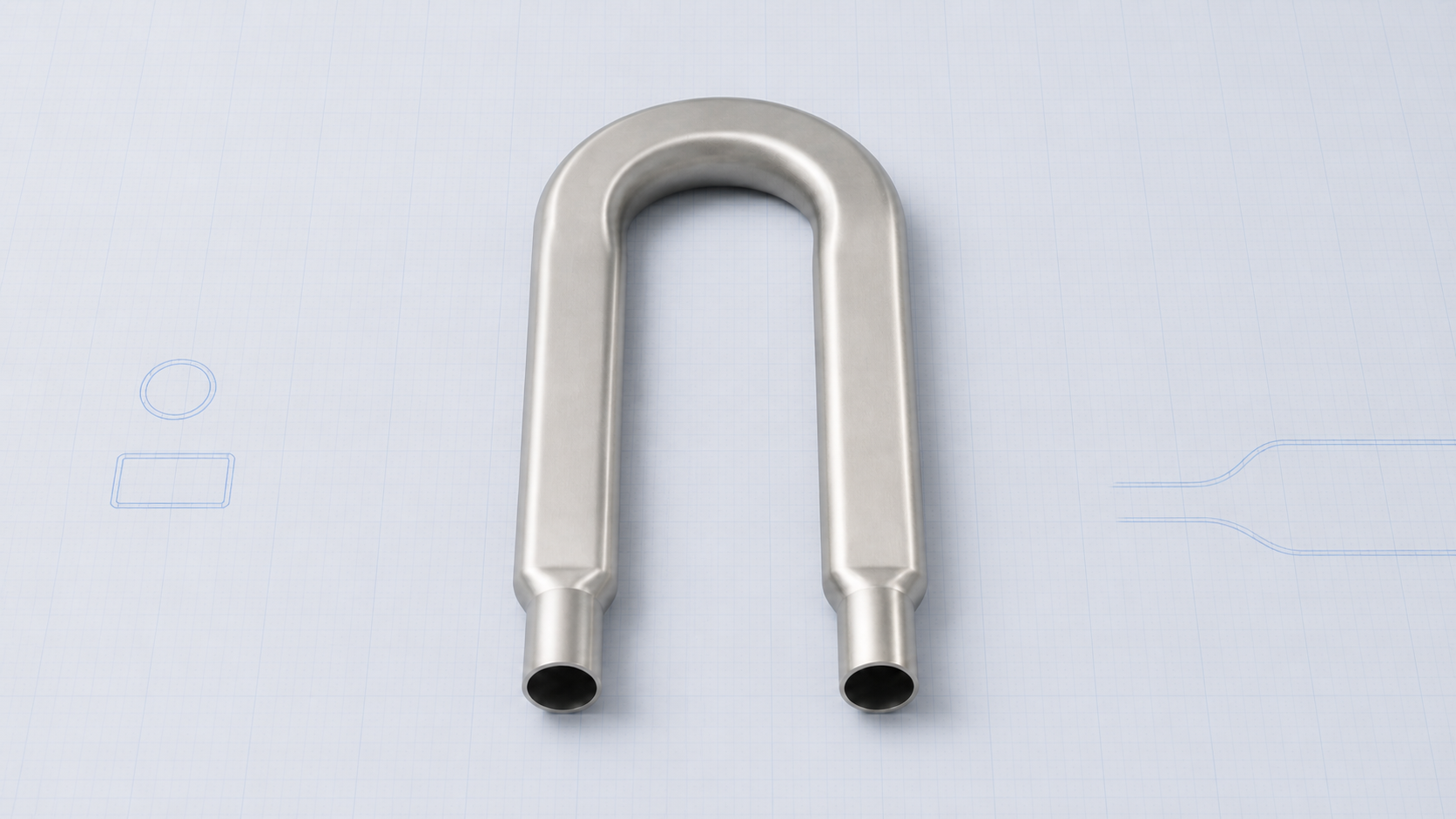
Section changes, the tube-end length available for sealing and axial feed, and the assigned stage for holes and trimming all affect the hydroforming route and tooling layout.
Explore this topic →02Materials
Hydroforming behavior depends on the tube actually supplied, not only the grade shown on the drawing. Wall thickness and tolerances, delivery condition, manufacturing route, weld condition, and measured properties all affect material selection and process validation.
Explore this topic →03Process
Wrinkling, thinning, underfilling, and bursting can result from the combined effects of geometry, friction, axial feed, internal pressure, preforming, and incoming tube condition. Defect location, first appearance, and cycle records help separate the main contributing factors.
Explore this topic →Project-specific next step
A real part still needs its own evidence.
General guidance can expose the right questions. Feasibility, scope and validation still depend on the actual drawing, tube, interfaces and delivery requirements.