
Start with one engineering question
Choose the article closest to the geometry, material, process, tooling, or sourcing decision in front of you.
Hydroforming Insights by ShuiYiYuan
A practical knowledge center for engineers, procurement professionals, and manufacturing teams evaluating hollow metal parts. Start with the geometry, material, interfaces, and delivered condition—then decide what the process can establish.
Drawing feasibility check
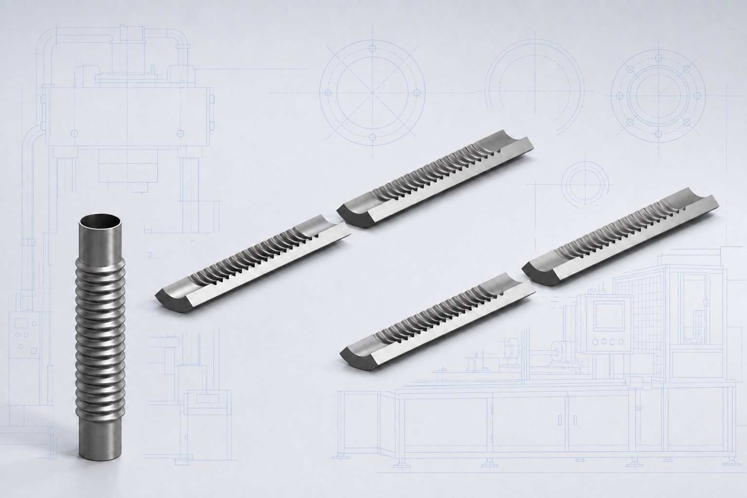
The drawing review establishes where and how much each section must expand, whether a bent section requires further expansion, and whether the tube ends provide enough length for sealing, axial feed, and final trimming.
These conditions affect material delivery to the forming zone and the space available for the die and end tooling. They also determine whether the next step is a geometry change, added process stock, simulation, or tryout.
Browse by decision
The six topics connect part geometry and material inputs with process behavior, tooling, application requirements, and project validation.
Section changes, the tube-end length available for sealing and axial feed, and the assigned stage for holes and trimming all affect the hydroforming route and tooling layout.
Explore this decision path →02Hydroforming behavior depends on the tube actually supplied, not only the grade shown on the drawing. Wall thickness and tolerances, delivery condition, manufacturing route, weld condition, and measured properties all affect material selection and process validation.
Explore this decision path →03Wrinkling, thinning, underfilling, and bursting can result from the combined effects of geometry, friction, axial feed, internal pressure, preforming, and incoming tube condition. Defect location, first appearance, and cycle records help separate the main contributing factors.
Explore this decision path →04Prototype and production tooling differ in validation purpose, service life, and maintenance requirements. Quotations should identify the tool structure, tryout and measurement scope, revision responsibility, documentation, and plans for continued use.
Explore this decision path →05Wall-thickness distribution, section ovality, springback, and seam orientation after bending continue to affect preforming, material delivery, corner filling, and final calibration. The forming route for an automotive tube must follow its actual geometry and interface requirements.
Explore this decision path →06A rack manifold or cooling-line assembly may combine a formed hollow core with cut ports, fittings, joints, supports, cleaning, and qualification. These articles identify which geometry could belong to hydroforming and which requirements must be handled by other operations or verified separately.
Explore this decision path →How to use the knowledge center
Choose the article closest to the geometry, material, process, tooling, or sourcing decision in front of you.
Compare the stated material, geometry, tooling, and validation conditions with the actual part before applying a conclusion.
Use the cited papers, standards, and specifications when a design or procurement decision needs deeper verification.
Latest technical articles
Browse the latest published technical articles.
Engineering
Use cross-section perimeter change to flag material demand, feed limitations, corner-fill risk, and sections that need simulation before tooling.
Read the technical article →Engineering
Define the blank end, sealing contact region, axial-feed/support region, final trim line, delivered end, and process stock before tooling release.
Read the technical article →Materials
Select hydroforming tube from its delivered condition, dimensions, seam, manufacturing history, measured properties, and the part’s forming route.
Read the technical article →Process
Learn why hydroformed tubes thin in some zones and thicken in others, where to measure, and how simulation and tryout support wall-thickness acceptance.
Read the technical article →Process
Diagnose tube hydroforming wrinkles by their location and timing, then check pressure, axial feed, die contact, friction, pre-bending, and tube variation.
Read the technical article →Tooling
Compare prototype, bridge, and production hydroforming tools by validation purpose, repeatability, serviceability, change control, and required results.
Read the technical article →Automotive
See how bend thinning, ovality, preform geometry, die loading, pressure, and axial feed interact before final automotive tube hydroforming.
Read the technical article →Liquid Cooling
Evaluate selected rack-manifold core features for tube hydroforming without treating simple branch studies as assembly or system qualification.
Read the technical article →Process
Diagnose tube hydroforming bursts and splits from failure location, crack direction, onset stage, process records, local wall data, and tube condition.
Read the technical article →Process
Diagnose tube hydroforming underfilling through the target contour, preform, die-contact sequence, pressure-feed record, friction, and local wall evidence.
Read the technical article →Materials
Define incoming-tube OD, local wall, ovality, roundness, straightness, end condition, ERW seam, and scarfed region by location and lot.
Read the technical article →Process
Read a project-specific tube hydroforming pressure–feed trace, distinguish punch travel from material delivery, and verify it against formed-part results.
Read the technical article →Engineering
Plan hydroformed-part inspection from tryout through repeat production by linking each characteristic, method, record, decision rule, and disposition.
Read the technical article →Engineering
Assign holes, ports, trim edges, and joining features to in-die or post-form operations while defining datums, edge quality, cleanliness, and acceptance.
Read the technical article →Knowledge site and commercial site
Hydroforming Insights explains engineering principles, manufacturing-feasibility methods, material behavior, process development, and tooling decisions.
When you need ShuiYiYuan to review an actual drawing, confirm manufacturing scope, or discuss a quotation, continue to HydroformingFactory.com.