
Summary
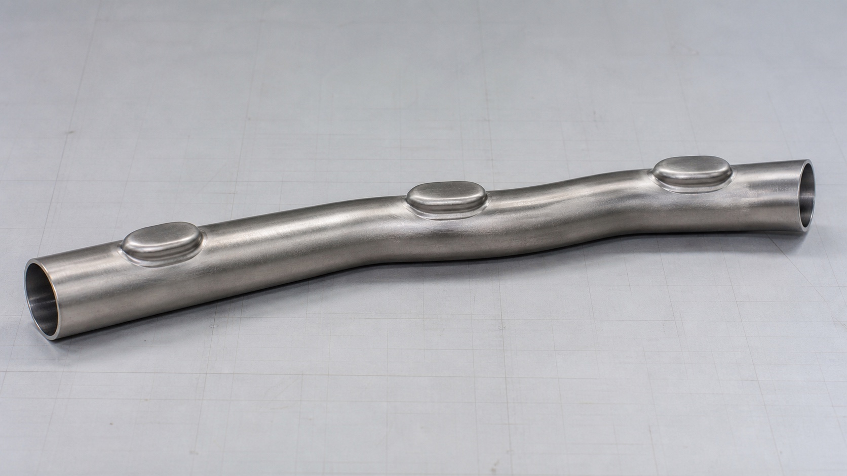
A rack-manifold project has three different engineering targets: the hollow core, the manifold assembly built around it, and the cooling system it serves. Hydroforming can shape only the deformable core and selected features within it.
A core-manufacturing review checks the starting tube, section changes, branch spacing, wall distribution, end-feed distance, sealing, counter-punch access, and die construction. Every cut port, fitting, seal, sensor, and joined interface needs its own downstream process and verification plan.
Published experiments report simple T- and X-branch forming within their specimen geometries and boundary conditions. They do not demonstrate a production route for a dense rack header with repeated outlets. Hydraulic performance and system qualification remain separate from forming feasibility.
On this page
Separate the core, manifold assembly, and cooling system
The term “rack manifold” can refer to three different engineering targets:
- Hollow core or header: the primary passage that carries coolant.
- Manifold assembly: the core after ports, fittings, quick disconnects, vents, drains, sensors, supports, seals, and joined parts have been added.
- Cooling system: the supply-and-return network that connects the manifold assembly to IT equipment and the rest of the facility or technology cooling loop.
Tube hydroforming acts on the deformable workpiece at the core level. Suitable transitions or branches may be integrated into that core, which can change the number or location of later joints. The pressure-forming operation does not produce every assembly interface and does not validate the cooling system.
Drawings, quotations, and validation plans should name the applicable level. Open Compute Project (OCP) documents describe manifold functions and qualification obligations, but they do not select a manufacturing route for the hollow core.
What published hydroforming studies actually show
Tube hydroforming uses internal pressure, sometimes with axial feed, to expand a tube against a die. A broad review treats changing closed sections, branches, preforming, axial feed, thickness distribution, and secondary operations as separate process-development problems (Bell et al., 2020). Controlled experiments have also formed simple T- and X-branch specimens and compared measured branch height and wall distribution with finite-element predictions (Ray and Mac Donald, 2005).
A simple T or X specimen is not evidence that a dense rack header with repeated outlets is production-ready. Adding branches changes the available feed length, material demand, wall distribution, seal arrangement, counter-punch access, and die space. Results from one specimen geometry and material cannot be extended to a different stainless-steel rack manifold.
Rack manifolds also use other architectures. One OCP-listed in-rack product uses a polymer distribution unit, so neither metal construction nor hydroforming is inherent to the product category. Machined blocks, welded or brazed headers, extrusions, castings, fabricated tube assemblies, and polymer systems each suit different interfaces, volumes, and validation plans.
Screen the core one feature at a time
Break the proposed core into individual features, then check each one against the starting tube, material-feed path, die access, finished interface, and required validation. The table separates published forming results from project development and work that belongs after core forming.
| Proposed feature | Published or project basis | Core-forming questions | Downstream work |
|---|---|---|---|
| Gentle local diameter or perimeter transition | No generic limit; project evidence required | Check required expansion, radii, starting wall, feed path, and calibration access | Tool tryout, wall and dimensional inspection, cleaning, and hydraulic assessment |
| Offset or locally flattened section | Project-specific | Define the preform, fold control, die-contact sequence, and final calibration | Packaging datums, supports, internal-flow-area effects, and pressure-drop analysis |
| Shallow local reservoir feature | Project-specific | Evaluate surface growth, axial feed, local thinning, drainage, and die access | Minimum-wall and volume checks, cleanliness, and product-pressure testing |
| T- or opposed branch concept | Simple specimens have been published | Develop branch spacing and height, wall distribution, end feed, material, and counter-punch access for the actual core | Port finishing, connector interfaces, joining where needed, flow characterization, and qualification |
| Local transition for a later sealing or press-fit interface | Interface evidence required | Form the transition only after its tolerance and surface can be produced and measured | Mating tolerance, insertion or retention force, seal behavior, and leak qualification |
| Repeated outlet holes | Normally a post-form operation | Map every opening and the remaining ligament; pressure forming does not create an open hole | Cutting, piercing, machining, collaring, joining, deburring, inspection, and debris control |
| Threaded port, quick disconnect, valve, vent, drain, or sensor boss | Added after the core is formed | Define the added component, attachment method, and required local core geometry | Component selection, joining, seals, loads, service access, and leak testing |
| Dual-plenum or internally divided body | Not produced by expanding a conventional single-passage tube blank | Select a different blank architecture or manufacturing route | Passage isolation, internal joining, inspection access, pressure drop, cleaning, and integration |
| Complete rack manifold | Beyond the core-forming scope | Do not use a formed-core result as evidence for a finished manifold | Assembly definition, controls, interfaces, hydraulic validation, qualification, documentation, and installation |
For any project-specific feature, tie the actual material and geometry to the tooling concept, sample stage, measurement plan, and finished interface.
A formed branch is not a finished port
A hydroformed branch pulls the wall of a closed tube into a protrusion. A cut port removes material, and a collared port reshapes the edge of an existing opening. Welded, brazed, threaded, and press-fit fittings create assembly interfaces. They may look similar on a finished manifold, but they have different tolerances, load paths, debris risks, and inspection methods.
Repeated outlets make spacing and tool access central to the route. One branch consumes material that might otherwise feed its neighbor. End seals, feed distance, counter-punches, and die construction can make some positions unreachable. Cutting holes after forming avoids branch expansion during the pressure cycle, but it introduces edge quality, ligament width, debris, heat input, and cleaning requirements. The finished-part drawing should identify how every interface is made.
A lower joint count can be a design target, but it is not an automatic result of hydroforming. The starting tube may contain a longitudinal weld, and ports, brackets, or fittings may still be joined after the core is formed.
Core geometry does not prove flow performance
A smooth, continuous core says little about hydraulic performance by itself. Flow distribution depends on the header section, supply-and-return arrangement, outlet spacing, branch and connector resistance, coolant properties, total flow, and the demand of connected devices.
OCP cooling-loop guidance describes the rack manifold as the device that distributes coolant to IT equipment and identifies pressure-drop and flow-distribution targets as design requirements. Forming can create part of the passage; it cannot establish those hydraulic results.
The as-built internal geometry is the hydraulic geometry. Wall movement can change local area and transition shape, while cuts, collars, seams, joints, and fittings can add restrictions. Flow simulation can guide development. Measurements of the completed assembly under defined conditions are needed to establish flow and pressure-drop performance.
Forming pressure is not a product pressure test
Pressure in the forming cycle is a manufacturing input. A rupture or gross pressure loss may become visible during that cycle, but the event is not a defined leak, proof, burst, fatigue, durability, life, or system-qualification test.
A product-pressure test needs a specified delivered configuration, closed interfaces, test medium, instrumentation, pressure, hold time, temperature, procedure, and acceptance criteria. The validation plan should assign ownership for the specification, execution, and disposition of results.
Integrity can change after holemaking, joining, heat or surface treatment, connector installation, and final assembly. Tests therefore may need to occur at more than one delivered state. A core that survived forming has not demonstrated the performance of interfaces added later.
Formability does not establish coolant compatibility or cleanliness
Formability and coolant compatibility answer different questions. A tube can form successfully and still be unsuitable for the selected coolant, joining combination, temperature, corrosion environment, or service plan. A compatible alloy or finish can also have too little forming margin in the available tube condition.
OCP documents, including the Open Rack V3 Blind Mate Manifold Specification, address wetted materials, finishes, seals, fluid compatibility, corrosion, and service conditions. They do not qualify “stainless steel” as one universally suitable material. The released design still has to specify grade, tube and weld condition, surface state, any required treatment, joining materials, elastomers, coolant chemistry, and galvanic combinations.
The cleanliness plan must account for forming fluid, lubricant, cutting particles, burrs, and joining residue. OCP documents assign cleanliness and compatibility responsibilities at the component or system level; they do not validate a particular cleaning, pickling, or passivation process. The project must specify and verify those operations separately.
Information needed before choosing the route
A core-feasibility review needs the following information under one controlled design revision:
- a 3D model and sectioned drawing of the proposed core, including any internal dividers;
- the incoming tube or blank specification, measured dimensions, wall tolerance, material condition, seam, and finish;
- a map of every expansion, offset, branch, socket, cut port, collar, fitting, bracket, and joined interface;
- port count, spacing, orientation, datums, and the connector or downstream component at each port;
- minimum-wall, dimensional, fatigue, pressure, corrosion, and cleanliness requirements by functional zone;
- definitions for the as-formed core, post-form core, and final-assembly delivery states;
- coolant, temperature and pressure conditions, flow range, pressure-drop target, and distribution objective;
- test and qualification procedures, ownership, and acceptance criteria;
- sample-validation scope and the controls expected in repeat production.
These inputs show whether the request concerns one local feature, a complete hollow core, or only a tube with a similar appearance. They also divide core-manufacturing work from connector design, rack hydraulics, coolant distribution unit (CDU) and cold-plate responsibilities, site integration, and system commissioning.
For a drawing review and manufacturing-scope discussion, ShuiYiYuan accepts data-center liquid-cooling piping and manifold-core enquiries through its commercial site.
Frequently asked questions
Is a hydroformed rack manifold a standard data-center product?
Can tube hydroforming produce a T-branch?
Can hydroforming create every outlet on the manifold?
Will a hydroformed core deliver equal flow at every port?
Does the forming pressure count as a product pressure test?
Is any stainless-steel core suitable for liquid cooling?
References
- Open Compute Project. Rack Manifold Requirements and Qualification Guideline.
- Open Compute Project. Cold Plate Cooling Loop Requirements, Revision 2.
- Open Compute Project. Open Rack V3 Blind Mate Manifold Specification.
- Open Compute Project. Liquid Cooling Integration and Logistics White Paper.
- Ray, P., and Mac Donald, B. J. “Experimental study and finite element analysis of simple X- and T-branch tube hydroforming processes.” International Journal of Mechanical Sciences 47(10), 1498–1518 (2005).
- Open Compute Project. “Georg Fischer LiquidCore In-rack Manifold.”
- Bell, C., Corney, J., Zuelli, N., and Savings, D. “A state of the art review of hydroforming technology.” International Journal of Material Forming 13, 789–828 (2020).