
Summary
Pressure stabilizes and expands the wall; the end punches feed material into areas that need it. If compression arrives before sufficient support, the tube may wrinkle or buckle. If pressure rises before enough material arrives, the same part may thin or burst instead.
The visible wrinkle can be downstream of the cause. Early die contact, a pre-bend, seal drag, or uneven lubrication may stop feed in one area and pile material up somewhere else.
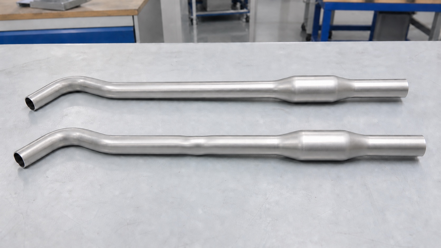
A temporary wrinkle is acceptable only when development trials show that it forms predictably, disappears completely during calibration, and leaves compliant wall thickness, geometry, surface, and performance. A remaining fold is not made acceptable by calling it a process aid.
On this page
First identify what you are actually seeing
Shop-floor descriptions often mix wrinkles, buckles, folds, and die marks. Before changing the recipe, describe the shape, locate it on the blank and tool, and determine when it first appears.
For this diagnosis, wrinkling means a local wall wave caused by compressive instability. Buckling is a larger loss of stability involving a longer tube segment or the tube axis. A fold is a severe local overlap or trapped wrinkle that may not calibrate out. A shallow line with no shape or wall buildup may instead be a die, lubricant, seal, or handling mark.
Each condition points to a different investigation. More pressure may suppress an early wrinkle while increasing thinning elsewhere. Less feed may clean up the tube end but starve a remote expansion. Polishing will not correct a pressure-and-feed mismatch, and recipe changes will not remove geometric interference.
Use the observed pattern to choose the next check rather than changing several settings at once.
| What you see | What to test | What to record | Do not assume |
|---|---|---|---|
| Short waves appear early in an unsupported span | Axial compression exceeds the wall’s current stability | Onset time or stroke, pressure, punch travel, unsupported length | Final calibration will always remove them |
| A wrinkle appears near a transition after die contact | Contact and friction block or redirect feed | Contact sequence, lubrication, surface marks, local wall map | More punch travel will deliver material to the remote zone |
| Large lateral or axial distortion | Global buckling, poor blank support, uneven feeding, or misalignment | Blank position, punch symmetry, seal contact, tool alignment | The distortion is merely cosmetic |
| A deep fold remains after calibration | The unstable wave became trapped before full die contact | Sectioned sample, fold depth, thickness and surface evidence | Higher calibration pressure alone is a safe fix |
| A wrinkle occurs near a pre-bend | Ovality, prior compression, or bend-induced wall variation | Pre-bent blank geometry and wall, seam orientation | Hydroforming created the entire defect |
| The wrinkle repeats with one lot or seam orientation | Incoming tube property, wall, weld, or surface variation | Material records, wall map, seam location, lot comparison | The nominal model represents every blank |
| Irregular shallow lines with no wall buildup | Tool, lubricant, seal, or handling imprint | Surface replication, cleaned-tool trial, dimensional check | Every visible line is a structural wrinkle |
More than one mechanism may be present. Record the starting condition and cycle before changing a variable.
Pressure and axial feed work as one timed path
A hydroforming cycle is a sequence, not a pair of final setpoints. The timing of pressure and punch movement determines whether the wall is supported, fed, and expanded in the intended order.
Koç and Altan describe process limits bounded by wrinkling, buckling, and bursting. Excessive early feed can destabilize an unsupported wall. Excessive pressure can produce high tensile strain and local failure. Insufficient feed can leave a large expansion thin. A usable path has to avoid all three outcomes.
Hama and co-authors simulated several paths for a rectangular die. In their case, raising pressure before axial pushing suppressed early local wrinkles and allowed feed to affect a larger central region. The result shows why early stabilization may matter; it does not prescribe a universal sequence or pressure.
Set the path from the actual:
- tube diameter, wall, length, and material response;
- section changes and target radii;
- pre-bend, ovality, and preform;
- unsupported spans before die contact;
- end-seal design and available punch travel;
- friction and lubricant distribution;
- feed access from each tube end;
- tool deflection, alignment, and machine response.
A useful problem statement is “the wrinkle starts here at this point in the cycle,” not “the pressure is wrong.”
The wrinkle may appear downstream of blocked feed
Axial feed helps only when material moves from the punches to the expansion. Die contact creates friction, and bends, tight transitions, contamination, uneven lubricant, or a weld bead can add resistance.
Material may pile up and wrinkle at one location because feed is blocked somewhere else. More punch travel can worsen the pileup. Compare punch displacement with the actual movement of marks or sections along the tube; do not assume every millimeter of stroke reaches the target.
The goal is repeatable friction, not the lowest possible coefficient. Control lubricant amount and application, die finish and cleaning, tube coating, and lot-to-lot surface condition.
Check the pre-bent blank and incoming tube
The blank does not enter the die as an ideal cylinder after pre-bending. The outside of the bend may be thinner and work-hardened, the inside may be thicker or already wrinkled, and the section may be oval. Each condition changes stiffness and die contact.
Flehmig, Blümel, and Kibben discuss the difficulty of pre-bending thin-wall, large-diameter tube to a small radius without buckling, cracking, or ovality. Their dimensions are study-specific, not a general limit. The measured pre-bent blank is part of the hydroforming input, even when the final cavity hides its starting shape.
Wall variation, temper, weld behavior, and residual stress can shift the onset of compression instability. When a wrinkle is intermittent, compare tube lot, seam orientation, wall map, lubrication, temperature, blank position, and machine records before treating it as random.
When a temporary wrinkle can be part of development
Yuan and co-authors investigated “useful” and “dead” wrinkles. In certain cases, controlled material accumulation acted as a preform and was expanded later into the cavity. Wrinkle number and shape also changed with loading path and length-to-diameter relationship.
The paper notes that one proposed small-wrinkle concept was not experimentally verified in that study. For an actual part, treat a temporary wrinkle as intentional only after physical development demonstrates that:
- it appears at the intended location and point in the cycle;
- it does not fold, pinch, crack, or trap lubricant;
- calibration removes it completely on physical samples;
- the finished wall and surface meet the specification;
- the part meets dimensional and functional requirements;
- the behavior repeats across the controlled incoming-tube range.
Without that evidence, a wrinkle remaining on the finished part cannot be accepted by assumption. The drawing, surface specification, functional requirements, and validation plan determine its formal disposition.
Run the investigation from recorded evidence
Unrecorded recipe changes can hide the mechanism. Work through the following sequence instead.
1. Tie the part to its cycle
Record the part revision, tube lot, seam orientation, lubricant batch, tool condition, machine recipe, and exact cycle. Mark the wrinkle relative to the die and tube ends.
2. Find when the wrinkle starts
Use interrupted trials, machine data, safe video where practical, or simulation to determine whether the wave begins during pre-closing, early feed, free expansion, die contact, or calibration.
3. Compare commands with the actual cycle
Compare pressure over time, left and right punch force or travel, seal behavior, and tool position. These records show whether the machine followed the intended path and whether the blank slipped or shifted.
4. Trace where material could and could not move
Check for early die contact, a bend or transition blocking feed, uneven lubrication, seal drag, weld-bead interference, and asymmetric tool contact. Use the measured pre-bent blank, not nominal CAD geometry alone.
5. Map the wall and the shape together
A local wall increase may show material accumulation. Severe thinning next to a wave may point to another instability or to calibration damage. Section or scan representative samples when the consequence justifies it.
6. Change one recorded hypothesis at a time
Use simulation or a planned tryout to test one documented hypothesis at a time. Define the variable, allowed range, stop criteria, and post-trial checks before running the comparison.
7. Recheck the finished part after the fix
After the visible wrinkle is gone, recheck minimum wall, geometry, interfaces, surface, and required functional performance. A smooth surface alone does not prove the correction is sound.
Frequently asked questions
What causes wrinkles in tube hydroforming?
Will more internal pressure remove a wrinkle?
What is the difference between wrinkling and buckling?
Can a small wrinkle be allowed before calibration?
Why did wrinkles start after a tube-supplier change?
Can simulation predict a hydroforming wrinkle?
References
- Koç, M., and Altan, T. “Prediction of forming limits and parameters in the tube hydroforming process.” International Journal of Machine Tools and Manufacture, 42(1), 123–138, 2002.
- Yuan, S., Wang, X., Liu, G., and Wang, Z. R. “Control and use of wrinkles in tube hydroforming.” Journal of Materials Processing Technology, 182(1–3), 6–11, 2007.
- Hama, T., Ohkubo, T., Kurisu, K., Fujimoto, H., and Takuda, H. “Formability of tube hydroforming under various loading paths.” Journal of Materials Processing Technology, 177(1–3), 676–679, 2006.
- Strano, M., Jirathearanat, S., and Altan, T. “Adaptive FEM Simulation for Tube Hydroforming: a Geometry-Based Approach for Wrinkle Detection.” CIRP Annals, 50(1), 185–190, 2001.
- Manabe, K., and Amino, M. “Effects of process parameters and material properties on deformation process in tube hydroforming.” Journal of Materials Processing Technology, 123(2), 285–291, 2002.
- Flehmig, T., Blümel, K. W., and Kibben, M. “Thin Walled Steel Tube Pre-Bending for Hydroformed Components — Bending Boundaries and Presentation of a New Mandrel Design.” SAE Technical Paper 2001-01-0642, 2001.