
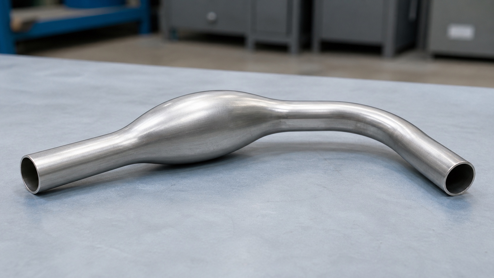
Summary
Wall thickness is a map, not one post-forming number. Bulges, tight corners, section transitions, and the outside of a pre-bend often deserve the first look; fed ends and constrained regions may thicken instead.
If finished wall is a delivery requirement, the drawing needs to state where it is controlled, what limit applies, how it will be measured, and at which production stage. A minimum-wall value with no location or method can miss the actual risk.
No thinning percentage is acceptable for every part. The limit follows the tube, geometry, service load, joining and fatigue requirements, measurement method, and customer specification. Where finished wall is a controlled delivery requirement, simulation can identify likely hot spots and measured samples can confirm the delivered condition.
On this page
Why expanded areas lose wall thickness
Internal fluid pressure pushes the tube toward the die cavity. If a region gains surface area faster than material can flow into it, that material has to spread over a larger area and the wall becomes thinner. Local bulges, branches, major section changes, and tight corners are common places to check.
End punches can feed material toward an expanding region and reduce thinning compared with pressure-only forming. Punch travel, however, is not the same as material delivered to the target. Bends, early die contact, and friction can absorb or block that movement.
Loading-path experiments also show that the sequence and combination of pressure and axial feed change material flow, wrinkling, and thinning. Hama and co-authors reported those effects for particular specimens and loading paths; the results do not establish one sequence for every part.
Koç and Altan describe a process window bounded by competing failure modes. Too little feed can leave an expanded zone thin. Too much feed, or feed applied at the wrong time, can cause buckling or wrinkles. Pressure that stretches the available material too far can promote necking or bursting; pressure that fails to stabilize the wall can allow compression instability before the cavity is filled.
The final wall therefore records the entire loading history, not just the calibration pressure at the end of the cycle.
Why fed and constrained regions can thicken
A wall thickens when compressive feed accumulates faster than the local surface expands. This can happen near the fed ends, at section transitions, or where die contact restrains movement. Whether that extra material is acceptable depends on fit, mass, fatigue, flow area, joining, and dimensional requirements.
The same compression that carries material into a forming zone can become unstable and form a wrinkle or fold. Read a thickness map alongside the part shape and cycle history. A high reading next to a wrinkle does not show that the part is stronger.
Judge local thickening against the drawing and the required functional tests. More metal is not automatically harmless when it changes an interface, a controlled dimension, or the inside passage.
Yuan's Modern Hydroforming Technology, second edition discusses axial feed, preforming, loading paths, and wall change in geometry-specific examples (printed pages 30, 42–45, 83–86, and 121–124). Those examples support the mechanisms described here; they do not set finished-wall limits for a new part.
Where to look first for a critical wall
The locations below are useful screening points. The actual critical wall must still be found from the part geometry, material, loading path, and measured samples.
| Zone to check | What may be happening | Question for the process review | Evidence to collect |
|---|---|---|---|
| Tight die corner | High local stretch as the wall fills the corner | Can the selected tube and material fill this radius, and is friction delaying feed? | Predicted strain and thickness, cut section, corner geometry |
| Large local expansion or protrusion | Surface area grows faster than material arrives | Can axial feed reach the feature, and is the starting section suitable? | Material model, loading-path study, minimum-wall readings |
| Outside of a pre-bend | Tensile strain and possible thinning from bending | How much forming margin remains after the bend? | Pre-bend inspection and comparison with the formed part |
| Inside of a pre-bend | Compression, ovality, or thickening may already be present | Did the bend introduce a wrinkle or restrict later feeding? | Ovality, wall map, and surface inspection |
| Tube end or punch-feed zone | Material enters under axial compression | Are sealing and feed stable at each active end? | Punch travel, seal marks, local wall, and geometry |
| Early die-contact zone | Contact and friction can restrict later flow | Does the tube lock against the die before a remote area fills? | Contact sequence from simulation or an instrumented tryout |
| Transition between sections | Bending, stretching, and compression occur together | Does the transition allow stable material flow? | Section cuts, local wall, dimensions, and surface condition |
| Around a post-form hole or trim | The formed wall may be thin before cutting | Will enough ligament and wall remain at the interface? | Wall before cutting, finished edge, and functional requirement |
Several of these conditions may occur on one part. If a minimum-wall callout is intended to control a critical zone, it needs a location, production stage, and measurement method.
Corner filling depends on more than radius
Kridli and co-authors studied a round tube expanded into a square die. In that case, die-corner radius, starting wall, and strain-hardening exponent affected corner fill, required pressure, and the final thickness distribution. The thinnest regions coincided with corners that were most susceptible to splitting.
The study does not supply a universal radius rule. It shows why radius, starting wall, material response, and process path have to be reviewed together. In an otherwise controlled comparison, a larger corner is less demanding to fill, but the neighboring section, feed path, and die contact still affect the result.
Friction may transmit load in one stage and block feed in another. Orban and Hu modeled a specific round-to-square case in which tube–die friction changed the thickness distribution. Lubricant, application consistency, tube surface, and die finish therefore belong in the controlled process definition. The answer is not simply to raise or lower friction everywhere.
The working interface needs to be repeatable and compatible with the validated loading path.
Measure the blank before blaming the forming cycle
Keep four quantities separate: the nominal starting wall stated on a drawing or tube standard; the actual incoming wall and its longitudinal and circumferential variation; the local wall distribution after pre-bending, preforming, hydroforming, and any relevant post-forming operation; and the delivery value judged at the specified location, stage, method, and sampling plan. A nominal incoming value cannot replace a finished local minimum.
Actual wall can vary around the circumference and along the length, with different patterns in welded, drawn, extruded, or sized products. Weld clocking and other manufacturing features may place that variation differently in the formed part. Pre-bending or preforming can add thinning, thickening, ovality, and local strain before hydroforming begins.
A model that starts with a perfectly uniform nominal wall can predict an optimistic minimum when production blanks vary. Where the design margin is narrow, use representative incoming distributions and material conditions rather than the nominal value alone. The incoming control plan should then keep production tube within the range used for validation and preserve the relevant seam or feature orientation.
Put the finished-wall requirement on the drawing
Separate the incoming-tube specification from the finished-part requirement. If finished wall is controlled, translate the delivery value into a requirement that can be measured and judged. A note such as “tube wall: X” is ambiguous unless it identifies the thickness quantity, location, production stage, and method.
As applicable to the part, a finished-wall requirement may specify:
- the controlled sections or zones;
- minimum wall, and a maximum where function requires one;
- areas excluded because later trimming removes them;
- measurement method and probe or tool access;
- the number and orientation of measurement points;
- the production stage and sampling frequency;
- how seams, transitions, and bends are handled;
- links to dimensional, leak, burst, fatigue, crush, or joining requirements.
Forming pressure is a manufacturing parameter; it does not demonstrate service-pressure capacity or service life. Wall measurement, leak testing, proof testing, burst testing, fatigue testing, and life testing answer different questions under their stated conditions. Use the checks required by the product or customer specification; none replaces all the others.
Choose the measurement method before setting acceptance
A cut section shows a local wall profile directly but destroys the sample. Mechanical measurement is possible only where the required surfaces are accessible. ISO 16809:2025 states principles for pulse-transit-time ultrasonic thickness determination by contact or immersion on metallic and nonmetallic materials. ASTM E797/E797M-21 covers manual contact pulse-echo thickness measurement from one side under stated material, temperature, and back-wall-echo conditions; it applies primarily to flat components with parallel surfaces and has limited applicability to nonparallel or concentric surfaces. Neither document sets project acceptance or proves that a particular hydroformed curve is measurable. The project plan still has to establish method suitability, access, calibration, uncertainty, locations, stage, sampling, and acceptance criteria.
Fix the method before interpreting the tolerance. Two methods may not sample the same point or average the same area. Sparse readings on convenient flat surfaces can miss a minimum at a sharp transition.
A practical validation sequence is:
- use geometry and simulation to identify likely high-risk zones;
- measure the pre-bent or preformed blank where prior strain matters;
- take denser readings on early tryout samples than in routine production;
- compare the measurements with the model and correct the assumptions;
- base production sampling on the verified critical zones.
Use simulation to find risk and tryout to verify it
Finite-element analysis can screen likely thinning, thickening, and instability zones and compare starting walls, materials, friction assumptions, corner radii, and pressure-and-feed paths before the tool is changed. Koç and co-authors combined geometry-specific FEA and design of experiments for simple hydroformed parts, considering branch height, thinning, and process variables together. That study supports comparative process development, not universal thinning limits.
Model accuracy depends on the geometry, mesh, contact and boundary conditions, tube-specific material data, friction, and how pre-bending and the weld are represented. Strano, Jirathearanat, and Altan describe adaptive simulation aimed at geometry-based wrinkle detection and loading-path adjustment. Even that narrower use depends on suitable inputs and physical confirmation.
Tryout and sample measurement show what the actual tool, lubricant, tube, seals, and controls produce. Only results collected under the defined acceptance plan can judge compliance. If measured and predicted thickness differ materially, investigate the material inputs, friction, contact, mesh, boundary conditions, measurement conditions, and process rather than hiding the mismatch in an average.
What a finished-wall requirement adds to project scope
Controlling the finished wall adds work beyond running the forming cycle. Depending on the part, the scope may include:
- reviewing the tube specification and delivered condition;
- simulation or another wall-thickness risk assessment;
- documenting the pre-bend or preform;
- setting sample quantities and a sectioning plan;
- reporting minimum wall by defined zone;
- revising the process after sample review;
- identifying whether measurement occurs before or after holes, trimming, joining, or heat treatment;
- controlling the tube source and process settings in repeat production.
The forming cycle makes the shape. This additional work verifies the wall condition that will actually be delivered.
For a drawing-specific review, use the hydroforming drawing-review checklist to assemble the tube specification, part geometry, controlled wall zones, inspection stage, and applicable acceptance requirements. A completed checklist supports scope definition; it does not by itself verify formability or compliance.
Frequently asked questions
Does every area of a hydroformed tube get thinner?
Where is the minimum wall usually found?
Can more axial feed prevent thinning?
What wall-thinning percentage is acceptable?
Can a simulation use nominal starting wall only?
Does forming pressure prove the part can hold service pressure?
References
- Koç, M., and Altan, T. “Prediction of forming limits and parameters in the tube hydroforming process.” International Journal of Machine Tools and Manufacture, 42(1), 123–138, 2002.
- Koç, M., Allen, T., Jirathearanat, S., and Altan, T. “The use of FEA and design of experiments to establish design guidelines for simple hydroformed parts.” International Journal of Machine Tools and Manufacture, 40(15), 2249–2266, 2000.
- Yuan, S. Modern Hydroforming Technology, 2nd ed. National Defense Industry Press. Relevant printed pages: 30, 42–45, 83–86, and 121–124. Catalog record.
- Hama, T., Ohkubo, T., Kurisu, K., Fujimoto, H., and Takuda, H. “Formability of tube hydroforming under various loading paths.” Journal of Materials Processing Technology, 177, 676–679, 2006.
- Bell, C., Corney, J., Zuelli, N., and Savings, D. “A state of the art review of hydroforming technology.” International Journal of Material Forming, 13, 789–828, 2020.
- Kridli, G. T., Bao, L., Mallick, P. K., and Tian, Y. “Investigation of thickness variation and corner filling in tube hydroforming.” Journal of Materials Processing Technology, 133(3), 287–296, 2003.
- Orban, H., and Hu, S. J. “Analytical modeling of wall thinning during corner filling in structural tube hydroforming.” Journal of Materials Processing Technology, 194(1–3), 7–14, 2007.
- Manabe, K., and Amino, M. “Effects of process parameters and material properties on deformation process in tube hydroforming.” Journal of Materials Processing Technology, 123(2), 285–291, 2002.
- Strano, M., Jirathearanat, S., and Altan, T. “Adaptive FEM Simulation for Tube Hydroforming: a Geometry-Based Approach for Wrinkle Detection.” CIRP Annals, 50(1), 185–190, 2001.
- ISO 16809:2025, Non-destructive testing — Ultrasonic thickness determination.
- ASTM E797/E797M-21, Standard Practice for Measuring Thickness by Manual Ultrasonic Pulse-Echo Contact Method.