
Summary
Pre-bending, preforming, and final hydroforming do three different jobs. The bend establishes the tube centerline. The preform prepares local sections and controls how the blank enters and contacts the die. Pressure and axial feed then expand and calibrate that prepared shape.
Each stage changes what enters the next: wall thickness, ovality, strain, springback, and surface contact. A bend can pass a centerline check yet leave too little wall for corner filling. A poor preform can trap a fold or create early die contact that blocks material feed.
Route development must therefore follow the same sequence as production: incoming tube, bending, preforming where needed, die loading, pressure and end feed, calibration, trimming, and validation.
On this page
Start with the full route, not the final die
An automotive tube can combine a curved centerline with changing sections, local expansions, offsets, and joining interfaces. A straight blank may not fit between the open die halves, or it may collapse as the die closes. Pre-bending brings the centerline close to the required package path before the pressure cycle begins.
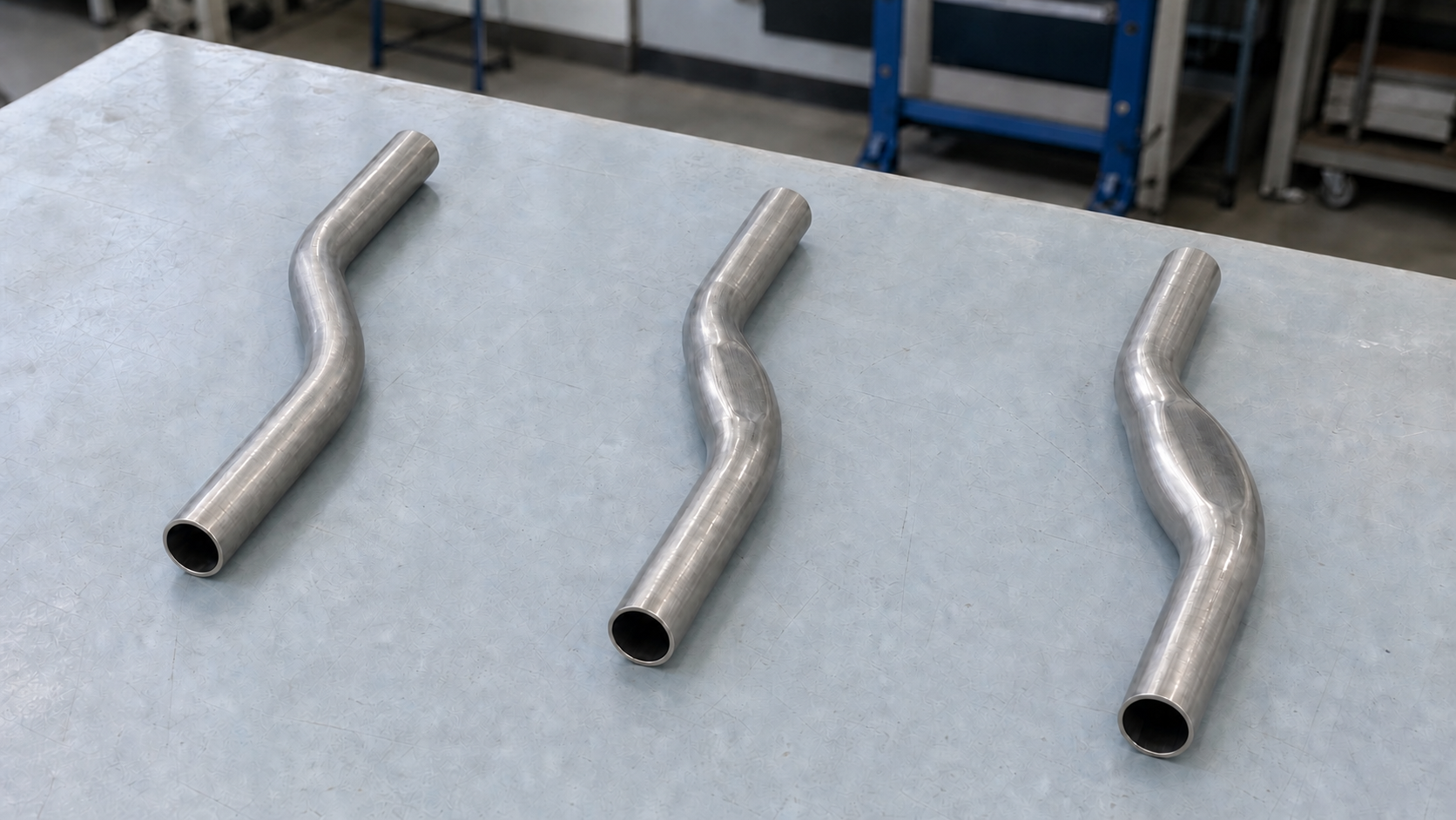
Preforming has a different job. It changes selected cross-sections or creates a controlled folded shape before final die closure. The intermediate blank does not have to look like the finished part; it has to load repeatably, close without an uncontrolled buckle, and place material where the final operation can use it.
Automotive process-development literature documents this staged approach. One frame-rail study used bending, pre-expansion, preforming, and final hydroforming. For that rail, the selected pre-expansion and folded preform improved the simulated strain distribution and material-feed response (Liu and Hahn, 2000). The result supports that project’s route; it does not establish four mandatory operations for every automotive tube.
Pre-bending sets the centerline—and changes the tube
The drawing may specify a centerline, but the bending operation also changes the wall thickness and cross-section that final hydroforming receives.
The outside radius is stretched and can thin. The inside radius is compressed and can thicken or wrinkle. A round tube can become oval, the bend can spring back, and the weld seam can move into a different position relative to a later high-strain zone. Tube diameter and wall, bend severity, material condition, mandrel and wiper support, lubrication, boost, and bending method all affect the result.
Research on thin-walled steel tubes shows why a relatively large diameter, thin wall, and tight bend are difficult to combine. The investigators examined buckling, cracking, ovality, and mandrel support within a defined test range (Flehmig, Blümel and Kibben, 2001). Their specimen dimensions are not universal limits. The work does show why a nominal centerline cannot fully describe the bent blank.
A thinned outside radius has less margin for later expansion. Ovality changes where the tube first touches the die. A shallow inside-radius wrinkle may open during one loading path but become trapped during another. The bending operation must therefore deliver a controlled blank condition, not merely a centerline that passes a checking fixture.
Final pressure cannot undo a poor bend
Internal pressure pushes the wall outward; it does not replace material lost from the outside radius or erase the tube’s strain history. Final calibration can correct a stable pre-bend within the developed process window. It cannot be expected to restore wall thickness, reverse work hardening, or open every buckle without causing another defect.
The University of Waterloo’s tube-bending and hydroforming program treats the two operations as a coupled sequence. Its published overview follows pre-bend thinning and ovality into the subsequent end-feed and hydroforming response instead of replacing the bent tube with an undeformed nominal blank. That distinction matters when the remaining ductility and prior strain influence the final failure margin.
A model that starts with a perfect round tube placed on the final curved centerline omits the deformation caused by bending. When the process window is narrow, the hydroforming model should begin from a defensible pre-bent geometry with its wall distribution, material state, and relevant boundary conditions. Measurements from physical bends are needed to check that representation.
Preforming prepares the blank for die closure
Preforming changes the blank before the final die closes. It can move existing material, alter first contact with the die, and open or restrict a later feed path. It cannot add material. Depending on the part, a preform can:
- reduce how far the die must move before it captures the tube;
- clear an interference that would prevent a round blank from loading;
- place more of the available wall near a later expansion or corner;
- control which surfaces touch the die first;
- turn an uncontrolled collapse into a repeatable intermediate shape;
- preserve access for sealing, orientation control, or axial feed.
The right intermediate shape depends on the part. A symmetric crush may work for a straight crossmember and misplace material in an offset rail. Local pre-expansion can delay contact in one zone while consuming strain margin in another. A folded preform is useful only when its location, depth, wall condition, and later loading path have been developed together.
Preforming can create new problems. Sharp tool contact can mark or thin the wall. Too much closure can make a dead fold that remains in the finished part. Poor orientation can move a weld seam or bend damage into a critical zone. Judge the preform by how it behaves in the next operation, not by how closely it resembles the final CAD surface.
Tune pressure and axial feed to the prepared blank
In final hydroforming, internal pressure stabilizes and expands the tube. End punches may also seal the blank and feed material toward an expanding section. Pressure, punch travel, friction, die contact, and the incoming preform act together; they cannot be tuned as independent settings.
Pressure applied too early can pin a broad area of tube against the die and restrict later feed. End feed applied before the tube is stable can cause compressive buckling. A preform that places material near the critical zone can reduce the distance it must travel; one that creates early contact can prevent the same nominal punch stroke from delivering material there.
Sequential simulation can transfer geometry, wall thickness, strain, and stress from bending and preforming into the final hydroforming analysis. The transfer must be set up and verified. If that work is needed, the quotation or project plan should state who supplies the upstream model, who performs the transfer, and how it will be checked.
Screen the route before tooling
| Observed part or blank condition | What it may mean for the route | Evidence needed for a decision |
|---|---|---|
| Long curved centerline with modest section change | Bending may do most of the shape development; a separate preform may not be needed | Measured bend geometry, ovality and wall distribution, plus a die-loading check |
| Tight bends combined with local expansion | Bend strain reduces the margin available for the later expansion | Tube-specific material data, a pre-bend wall map, sequential simulation, and sample sections |
| Major transition from round to non-round section | The blank may need a controlled crush or another preform before final die closure | Defined intermediate sections, contact sequence, corner-fill results, and wall-thickness results |
| Offset rail or asymmetric crossmember | A symmetric preform may place material on the wrong side of the part | Sections at defined stations, orientation control, and a pressure–feed study |
| High-strength or lower-ductility tube | Strain from bending and preforming may reduce the final forming margin | Properties from the actual tube, a bend-history model, a stated fracture criterion, and physical tryout |
| Welded tube | Seam position and local property variation may affect bending and final expansion | Tube construction, controlled seam orientation, and evidence from bent and formed parts |
| Dense holes, slots, brackets, or joining interfaces | Many of these features may be added after forming | A finished-part drawing, the cutting and joining sequence, and edge and interface validation |
This is an early route screen, not an automotive standard or a table of allowable values. A route decision still needs the specified tube, part geometry, modeling assumptions, and physical evidence. When sequential simulation is part of the plan, define the transferred state and the method used to validate it.
Information needed to define the route
Before selecting tooling or quoting development work, place the following information under the same part revision:
- final 3D geometry and section cuts through bends and transitions;
- the incoming tube specification, measured dimensions, wall tolerance, manufacturing route, and weld condition where applicable;
- centerline, bend radii, straight lengths, end condition, and orientation datums;
- zones controlled for minimum wall, section shape, crash or fatigue function, joining, and package clearance;
- which features come from hydroforming and which are added by cutting, piercing, machining, welding, or assembly;
- the existing preform or intermediate-blank data, if a route has already been developed;
- sample condition, measurement method, acceptance criteria, and the intended repeat-production state;
- revision status for the part geometry, tube source, material condition, and downstream interfaces.
With those inputs, the scope can distinguish final hydroforming of a supplied blank from a program that also includes bend development, preform development, tooling, tryout, and sample validation. A centerline approval then remains separate from approval of wall thickness and cross-section.
A bent or non-round tube is not proof of hydroforming
Appearance alone does not identify the manufacturing route. Bending can make a curved tube without changing its section. A constant non-round profile may be extruded, drawn, or roll formed before bending. A fabricated rail may use stamped shells and welds. Conversely, a hydroformed part can be trimmed, pierced, joined, coated, and assembled until the original pressure-formed surface is difficult to recognize.
Use drawings, process records, tooling, sample history, or other traceable manufacturing information to identify the route. A photograph of a smooth curved tube or irregular chassis section is not enough. The distinction matters when comparing an extruded aluminum rail or a conventional bent exhaust tube with a closed section expanded or calibrated by internal pressure inside a die.
When hydroforming adds no clear value
Automotive use and geometric complexity do not, by themselves, justify hydroforming. Bending may be enough when the section remains constant and only the centerline changes. Extrusion can supply a constant aluminum profile. Stamped-and-welded construction may provide better access or simpler joining, while casting may suit an integrated node.
Choose the route against the required section, material behavior, structural function, interfaces, production quantity, tooling plan, validation requirements, and available manufacturing chain. The result may be hydroforming, a hybrid sequence, or a different process.
For a drawing-specific review, ShuiYiYuan’s commercial site describes its automotive tube hydroforming project-evaluation scope. The quotation should identify the included operations, such as bending, preforming, tooling, hydroforming, and post-form work.
Frequently asked questions
Does every automotive hydroformed part require a pre-bend?
What is the difference between pre-bending and preforming?
Will final hydroforming correct ovality from bending?
Why include the bending result in a hydroforming model?
Does a non-round automotive tube prove it was hydroformed?
Can a pressure–feed curve be copied to a similar part?
References
- Liu, J., and Hahn, D. “Optimization of Process and Tool Development for Hydroformed Frame Rail Using FEM Simulation.” SAE Technical Paper 2000-01-0408 (2000).
- Flehmig, T., Blümel, K. W., and Kibben, M. “Thin Walled Steel Tube Pre-Bending for Hydroformed Components—Bending Boundaries and Presentation of a New Mandrel Design.” SAE Technical Paper 2001-01-0642 (2001).
- Qian, Y., Cattran, D., and Karima, M. “Towards Further Understanding of the Mechanics of Tube Hydroforming.” SAE Technical Paper 982276 (1998).
- WorldAutoSteel. Steel E-Motive Engineering Report.
- University of Waterloo, Waterloo Forming and Crash Lab. “Tube Bending and Hydroforming.”
- Bell, C., Corney, J., Zuelli, N., and Savings, D. “A state of the art review of hydroforming technology.” International Journal of Material Forming 13, 789–828 (2020).