
Summary
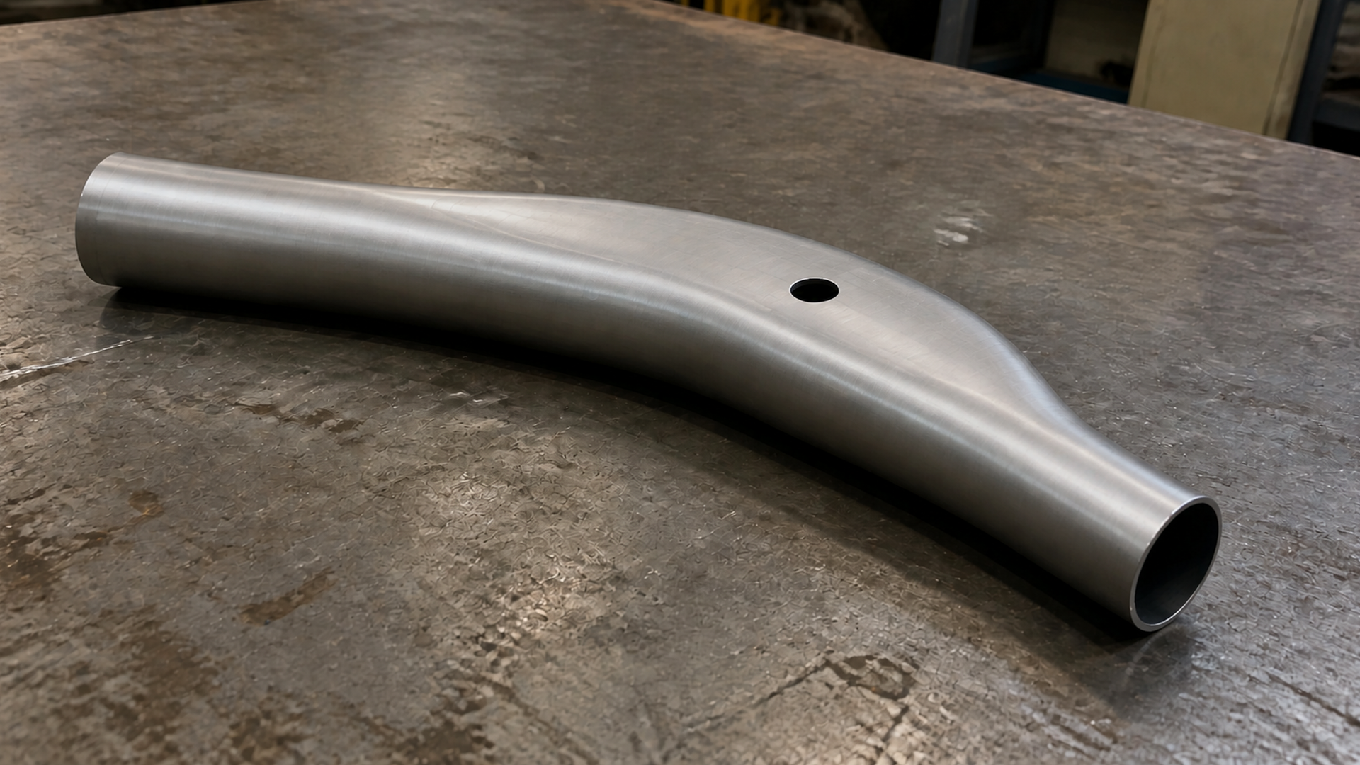
A finished hole, port, trim edge, and joining interface are different engineering objects. Each needs its own geometry, datum, edge condition, cleanliness, load, and finished-part requirements before an operation can be selected.
In-die hydropiercing is a specialized research and tooling route performed after forming but before unloading and part removal. Published results depend on the material, wall, local forming history, pressure support, punch direction, clearance, and feature shape.
Post-form cutting and joining avoid reopening the pressure boundary during forming, but add fixturing, access, datum-transfer, heat, debris, cleanliness, and acceptance questions. Project-agreed laser cutting and assembly or value-added support must be confirmed in the quoted scope.
On this page
Separate the finished hole, port, trim edge, and joining interface
An opening is defined by its size, profile, location, and orientation. A port or joining interface may also include a collar, boss, insert, fitting, sealing surface, load path, clearance envelope, and downstream assembly requirement. Treating all of them as a single “hole” leaves the manufacturing route and finished-part condition undefined.
Define the finished feature independently of the operation used to make it. A drawing can require a located opening without prescribing whether it comes from an in-die research process, post-form laser cutting, another separately sourced operation, or an assembled interface.
| Finished feature | Information to define | Keep separate |
|---|---|---|
| Hole or slot | Profile, size, location, orientation, datums, edge condition, and allowed local contour change | The operation used to create it |
| Port | Opening geometry, sealing or mating surface, fitting envelope, orientation, cleanliness, and service interface | Port fabrication, joining, and system qualification |
| Trim edge | Final contour, datum relationship, edge condition, access, and finished length | Blank process stock and the cutting operation |
| Joining interface | Mating part, fit, load direction, material compatibility, surface condition, and acceptance requirement | The selected joining method and supplier scope |
Keep the pressure boundary closed through the forming cycle
Direct tube hydroforming depends on a controlled pressure boundary inside the blank. A pre-existing opening can release pressure medium unless the tooling provides a specific seal, isolation feature, or other engineered arrangement. A finished hole on the drawing therefore cannot be transferred automatically to the incoming blank.
End trimming, sealing contact, and axial-feed or support space also compete for the tube end. Their relationship should be checked against Tube-End Sealing, Feed Length, and Trim Stock rather than inferred from the final edge alone.
| Possible stage | Primary engineering question | Required boundary |
|---|---|---|
| Before forming | Can the pressure boundary and material around the opening be controlled throughout forming? | Do not assume feasibility without a defined seal or isolation arrangement |
| In the forming die | Can a specialized piercing action occur after forming while pressure still supports the wall? | Treat hydropiercing as a dedicated tooling and development decision |
| After part removal | Can the part be located, supported, accessed, and cut without losing the required feature relationship? | Define fixture, datum transfer, edge, debris, and cleaning requirements |
| During assembly | Does the opening become a port or joint only after another component is added? | Define interface and joining responsibility separately from tube formation |
What published hydropiercing studies establish
Hydropiercing is a specialized in-die process performed after the tube reaches its formed state but before pressure is unloaded and the part is removed. Asnafi and coauthors tested inward piercing, inward slug folding, and outward piercing on specified AA6063-T4 extruded tubes. Their results show that piercing direction, pressure support, edge deflection, and slug handling interact; their material, dimensions, pressure, and criterion are not transferable design values.
Liu and coauthors found within their tests that tube properties and internal pressure changed collapse and fracture around a hydropierced opening. Wu and coauthors included the preceding hydroforming state when modeling rollover, sheared and fractured zones, tearing angle, and local fracture. These works support reviewing the actual tube, locally formed wall, pressure support, punch direction, clearance, and hole shape together; they do not create a universal process window or simulation method.
| Hydropiercing condition | Possible result affected | Still requires a defined project basis |
|---|---|---|
| Punch direction and tooling | Slug direction, edge rollover, or local deformation | Slug removal and whether retained debris is permitted |
| Internal-pressure support | Local collapse, shearing, and tearing | A suitable range for the actual material and feature |
| Material, wall, and prior forming | Local wall state and fracture sequence | Incoming tube and formed local condition |
| Hole shape and corners | Different fracture timing around the perimeter | Feature-specific locations and criteria |
| Clearance and constraint | Sheared zone, fractured zone, and edge deformation | Dedicated tool design and validation |
Hydro-burred collars and inserted ports require a dedicated route
Hydro-burring is not another name for making a plain hole. It forms a collar around an opening with pressure and dedicated tooling, so collar height, direction, thinning, cracking, mating geometry, and interface performance all require separate definition.
Mizumura, Sato, and Kuriyama studied a dedicated sequence combining hydropiercing, hydro-burring, and nut inlaying. Their specimens show that a formed connection concept can depend on pressure, flange formation, cracking behavior, and insert retention. The reported result remains specific to the stated specimens, tooling, and loading conditions.
- define the final collar direction, height, opening, radius, and adjacent wall requirement;
- define insert position, orientation, fit, retention, and load requirement;
- do not accept a formed interface on hole diameter alone;
- separate the opening, collar, insert, joint, and completed assembly;
Post-form cutting requires its own locating and edge plan
Moving a hole or trim edge after forming keeps it outside the pressure cycle, but the part must then be located and supported without distortion. The cutting head needs access, and the finished feature must retain its relationship to the functional datums.
ShuiYiYuan can provide laser cutting support for project-agreed contours, holes, or trims. The quotation and process plan must identify the feature, fixture and datum approach, edge condition, cleaning requirement, and required part condition.
| Planning question | Why it matters | Project record |
|---|---|---|
| Which surfaces locate the formed part? | Springback and formed variation may make a nominal CAD surface unsuitable as the only fixture reference | Datum scheme and fixture concept |
| Can the feature be reached? | Curved sections, opposite walls, and nearby features may restrict access | Access review and operation sequence |
| What edge and surface condition is required? | The process can affect edge profile, heat input, discoloration, or local distortion | Feature-specific edge and surface requirement |
| Where do slugs or residue go? | Debris can remain in a closed section or contaminate a sealing or joining surface | Debris-control and cleaning requirement |
| How is location verified? | A complete-looking feature may still be wrong relative to the functional datum | Agreed method and acceptance record |
Post-form laser cutting is one possible allocation, not a universal substitute for in-die work. Any additional cutting or machining step must be defined separately by feature, datum, edge condition, cleanliness, and acceptance requirements.
Specify fittings, sealing faces, and joint responsibilities separately
A cut opening does not complete a port. A fitting, sleeve, nut, bracket, sealing face, or other component may carry load or contain fluid. The opening and completed interface should be specified as separate stages so that deformation, joining, cleaning, and verification are not hidden behind one feature callout.
| Interface content | Requirement to define | Responsibility to assign |
|---|---|---|
| Fitting or sleeve | Position, orientation, mating surface, and projection | Part supply, locating, joining, and verification |
| Sealing surface | Controlled area, geometry, surface, and cleanliness | Opening manufacture, fitting installation, and functional confirmation |
| Bracket or connector | Datums, attitude, load direction, and assembly envelope | Boundary between formed-part and assembled-part acceptance |
| Welded joint | Applicable drawing symbol, joint form, and project specification | Process definition, execution, inspection, and approval |
| Threaded or mechanical interface | Thread or fit and retention requirement | Opening, processing, assembly, and final confirmation |
ISO 1101:2017 and ISO 5459:2024 can support geometric requirements and datum systems. ISO 2553:2019 and ISO 5817:2023 support welding symbols and imperfection language within their scopes. They do not choose a joining process or create a hydroforming tolerance.
Welding, brazing, press fitting, and threaded interfaces have different material and validation requirements. ShuiYiYuan can include assembly or value-added support in a proposal once the interface and responsibility are defined for the project.
Accept the formed part, opening, joint, and assembly at their own levels
A conforming formed part, hole edge, joined fitting, and completed assembly are four different conclusions. A forming-pressure record does not prove a port pressure rating, and a clean-looking opening does not prove joint strength or system performance.
Sun and coauthors observed different fracture timing at the corners and side midpoints of a specified DP600 square-tube and square-hole specimen. The work shows that locations around one feature can behave differently; it provides no universal edge limit for another material or hole shape.
| Acceptance object | Items to define | What it cannot prove |
|---|---|---|
| Formed tube | Geometry, datums, wall where controlled, surface, and process stock | Hole quality, joint integrity, or assembly performance |
| Hole, port, or trim edge | Location, orientation, profile, size, local contour, edge, residue, and cleanliness | Strength or sealing of a later joint |
| Joined interface | Fit, position, joint condition, retained geometry, and specified joint records | Complete pressure-boundary, fatigue, or system performance |
| Delivered assembly or system | Only tests and criteria explicitly assigned by the product specification and agreed scope | Conditions or service life beyond the defined test scope |
Overall tryout, first-production, lot, and repeat-production controls belong in Hydroformed Part Inspection and Acceptance Planning. This page only defines feature-level requirements for holes, trims, and joining interfaces.
Inputs required to assign the manufacturing route
Place the finished-feature and manufacturing-scope information under the same drawing revision. A useful review package includes:
- the final model and drawing with every hole, port, slot, trim edge, and joining interface identified;
- feature profiles, sizes, locations, orientations, tolerances, and datum references;
- required edge, surface, residue, and cleanliness conditions;
- the incoming tube, formed geometry, expected local wall condition, and surface restrictions;
- mating parts, fitting envelopes, assembly access, and functional interface requirements;
- which features are required before forming, in the forming die, after removal, or during assembly;
- the proposed owner of each cutting, joining, cleaning, inspection, and approval step;
- the inspection stage, method, sampling, and decision criteria required by the project;
- the required finished-part condition and operations outside the supplier scope.
Submit these inputs through the Tube Hydroforming Services page for a scope review. The team can assess the hydroforming portion and whether project-agreed laser cutting or assembly and value-added support belongs in the proposal.
Frequently asked questions
Can every hole be made in the tube before hydroforming?
Is hydropiercing the same as making a hole after hydroforming?
Does higher pressure always produce a better hydropierced hole?
Is post-form laser cutting always better than in-die piercing?
How is hydro-burring different from hydropiercing?
Does an acceptable hole edge prove that a port or joint is acceptable?
What information is needed to assign holes and ports to a process stage?
References
- Asnafi, N., Lassl, G., Olsson, B., and Nilsson, T. “Theoretical and Experimental Analysis of Hydropiercing.” SAE Technical Paper 2003-01-2884 (2003).
- Liu, G., Lin, J.-F., Wang, G., Su, H.-B., Chen, X.-P., and Jiang, H.-M. “Influence of tube properties on quality of hydropiercing.” Transactions of Nonferrous Metals Society of China 21, Supplement 2, s456–s460 (2011).
- Wu, Z. G., Li, S. H., Zhang, W. G., and Wang, W. R. “Ductile fracture simulation of hydropiercing process based on various criteria in 3D modeling.” Materials & Design 31(8), 3661–3671 (2010).
- Sun, L., Wang, X., Wang, Q., Fan, Z., Ling, C., Liu, X., and Chu, G. “Experimental and Numerical Investigation on the Square Hole Hydro-Piercing Process.” Metals 13(6), 1107 (2023).
- Shiomi, M., Ueda, Y., and Osakada, K. “Piercing of Steel Sheet by Using Hydrostatic Pressure.” CIRP Annals 55(1), 255–258 (2006).
- Mizumura, M., Sato, K., and Kuriyama, Y. “Development of Nut-Inlaying Technique in Hydroformed Component by Hydro-Burring.” Materials Transactions 53(5), 801–806 (2012).
- ISO 1101:2017, Geometrical product specifications (GPS)—Geometrical tolerancing—Tolerances of form, orientation, location and run-out.
- ISO 5459:2024, Geometrical product specifications (GPS)—Geometrical tolerancing—Datums and datum systems.
- ISO 2553:2019, Welding and allied processes—Symbolic representation on drawings—Welded joints.
- ISO 5817:2023, Welding—Fusion-welded joints in steel, nickel, titanium and their alloys—Quality levels for imperfections.