
Summary
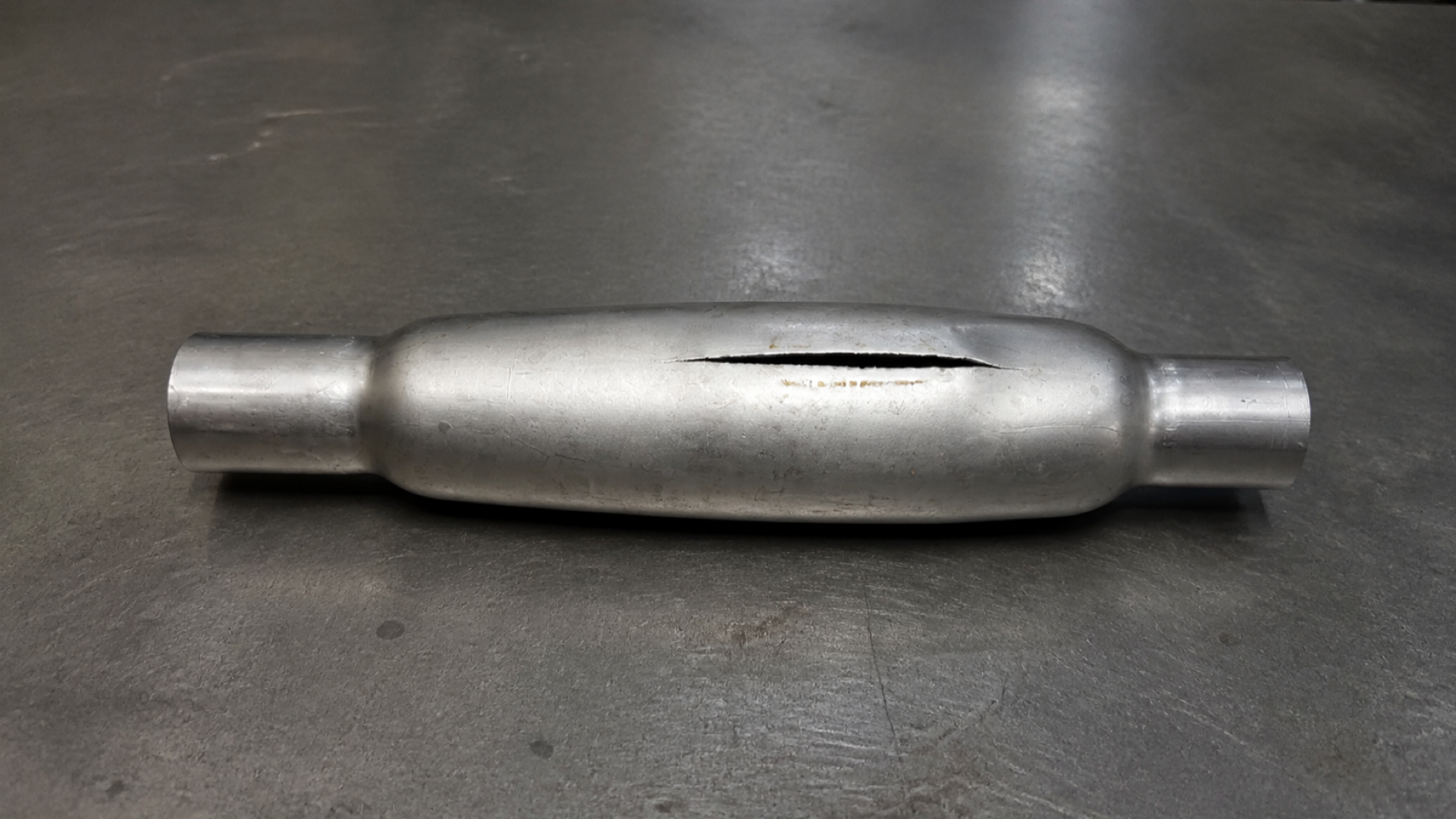
Burst onset and a visible split are related observations, not guaranteed to be two separately observable events. The final opening can extend after localization begins, so its length and direction cannot identify one cause by themselves.
The strongest record combines the physical sample with the actual cycle: part and tube traceability, fracture coordinates, pressure, left and right punch motion or force, die position, pressure-loss timing, local wall near and away from the fracture, seam orientation, and the pre-bent or preformed condition.
No universal burst pressure, fracture strain, thinnest location, or crack direction applies to every tube and part. Controlled repetition can strengthen or reject a project-specific hypothesis, but it does not turn a forming-cycle rupture into product proof, burst, fatigue, or life validation.
On this page
Start with the first confirmed failure event
Begin with the earliest event that can be tied to a specific part and cycle. That may be a visible line on an interrupted sample, an abnormal pressure loss, a change in punch response, or the first fully opened split. Do not assign the time of onset from the final opening alone.
Xia describes burst onset as a localized instability and splitting as the visible opening that generally follows in the investigated tubular hydroforming analysis (Xia, 2000). Published papers also use burst, rupture, fracture, and split differently. A shop-floor record should therefore state what was actually observed instead of claiming two distinct stages when the process did not resolve them.
| Record | Capture before changing the process | What it establishes |
|---|---|---|
| Part and tube identity | Part revision, tube source and lot, blank orientation, seam position where applicable | Which material and geometry entered the failed cycle |
| Cycle identity | Recipe revision, cycle number, date or sequence, tool and setup condition | Which recorded loading history belongs to the sample |
| First confirmed abnormal event | Stage, time or stroke, pressure behavior, punch response, visible indication | The earliest supported event—not the unobserved start of localization |
| Final sample condition | Uncleaned photographs, fracture coordinates, retained mating pieces and nearby surface marks | The condition available for later comparison |
Locate and orient the fracture
Describe the fracture in part coordinates: its axial and circumferential position, direction, length, branching, and relationship to a bend, section transition, die-contact boundary, weld seam, tube end, trim zone, or local surface mark. Mark the same coordinates on the blank, tool, and process model when those records exist.
Chu and Xu reported axial splitting in their free-bulge analysis of aluminum extrusion tubes and examined how material, tube dimensions, pressure, and end feed affected competing instabilities (Chu and Xu, 2004). That study does not make an axial split a universal signature or transfer its specimen limits to a closed die, welded tube, or pre-bent part.
Korkolis and Kyriakides showed in anisotropic aluminum-tube inflation experiments that loading path and material anisotropy can change localization and fracture orientation, and that predictions do not agree equally well under every modeled condition (Korkolis and Kyriakides, 2008). Crack direction is therefore one item of evidence, not a stand-alone verdict that pressure was too high or that one material feature was defective.
- record both ends of the visible opening and any branches or secondary cracks;
- measure its position from stable part datums rather than from a torn edge;
- note whether it crosses or follows a seam, tool witness, bend tangent, or section boundary;
- retain an unfailed comparison part and, where possible, an interrupted sample from an earlier stage.
Reconstruct pressure, feed, and contact on one timeline
A final pressure value cannot reconstruct the cycle. Place internal pressure, left and right punch travel or force, die or clamp position, and any abnormal fluid loss on one time or stroke axis. Use actual feedback where available; commanded values do not prove that the machine, seal, blank, and tool followed the intended path.
| Cycle interval | Records to align | Question for the investigation |
|---|---|---|
| Loading and closure | Blank position, die position, seal engagement, initial punch force | Was the tube located, supported, and sealed as intended? |
| Early pressurization or free expansion | Pressure rise, first punch motion, unsupported length, first visible change | Did tensile localization or compression instability begin before broad die support? |
| Axial feed and progressive contact | Left/right punch response, pressure, contact marks, material-marker movement | Did commanded motion deliver material toward the fracture region, or was movement blocked elsewhere? |
| Final die filling | Pressure slope, punch force or travel, die position, pressure-loss event | Did the first confirmed failure occur before, during, or after final contact? |
Pressure, axial feed, end constraint, friction, and contact act as a coupled loading history. More feed does not guarantee that material reaches the fracture region, and lowering pressure does not guarantee a stable alternative path. Any proposed change must be tied to the stage where the evidence places the instability.
Compare the fracture neighborhood with control locations
Examine the fracture neighborhood and at least one comparable unfailed location. Record local wall, tube surface, seam position, contact marks, pre-bend or preform geometry, and the incoming lot. The comparison should use identified coordinates and production stages; one wall reading beside an enlarged opening cannot recreate the original distribution.
Hama, Asakawa, and Makinouchi analyzed breakage in a multi-stage automotive part by considering deformation accumulated through pre-bending, die closing, and hydroforming, including the modeled weld region (Hama, Asakawa, and Makinouchi, 2004). Their material, geometry, boundary conditions, and results belong to that part. A crack near a seam does not by itself prove that the seam caused it.
Stevenson, Ng, and Polidoro likewise examined internally pressurized bent tubes as products of a prior manufacturing and deformation history (Stevenson, Ng, and Polidoro, 2004). The transferable lesson is to retain the preceding tube and bend history when interpreting the failure—not to assign every bent-tube failure to bending.
- compare the failed tube with an unfailed part from the same lot and recipe;
- compare the same part location across lots, seam orientations, or controlled setup conditions;
- separate incoming wall, pre-bend or preform wall, and post-form wall observations;
- record whether the final opening removed material that would otherwise have been measured.
Separate competing hypotheses before changing the process
Build more than one hypothesis from the combined sample and cycle record. A fracture can reflect several interacting conditions, and the visible opening may lie downstream of the earliest localization. Rank each hypothesis by what supports it, what contradicts it, and what controlled observation would distinguish it from the alternatives.
| Hypothesis group | Evidence to compare | Conclusion that is not justified alone |
|---|---|---|
| Incoming tube or local material response | Lot, delivered condition, actual wall, seam orientation, surface and available material records | A nominally compliant grade must be formable, or a nearby seam must be the cause |
| Local geometry and contact | Transition shape, bend, unsupported span, die witness marks and contact sequence | The final fracture coordinate is automatically the original localization coordinate |
| Pressure–feed path and end constraint | Actual pressure, both punch responses, seal or support behavior and the first abnormal event | Peak pressure or total punch travel identifies one setting as the cause |
| Prior bending or preforming | Measured intermediate geometry, wall, strain-history representation and orientation | Every fracture near a bend was created entirely by the bend |
| Friction, lubrication, or setup variation | Surface marks, lubricant application, blank position, tool condition and repeat-cycle records | One clean or failed sample establishes a stable process trend |
A simulation may compare these hypotheses only when its material response, geometry, contact, boundary conditions, and prior history represent the investigated part closely enough and are checked against physical evidence. A predicted high-risk location is not a measured failure result.
Use controlled repetition to test the leading hypothesis
First determine whether the failure repeats under the recorded condition. Then compare one defined change at a time, with the same tube range, measurement coordinates, sample handling, and post-cycle checks. Multiple simultaneous recipe or setup changes may remove the visible split while leaving the mechanism unresolved.
- state the hypothesis and the observation expected if it is correct;
- define the controlled variable, allowed range, sample count, stop condition, and safety authorization;
- retain the original condition as a comparison rather than relying on memory;
- record the full cycle and inspect both the former fracture zone and any new risk location;
- repeat only within the project’s approved tooling, equipment, material, and test plan;
- classify the result as supported, weakened, contradicted, or still unresolved.
A change that moves the fracture, delays it, or eliminates it in one sample is useful evidence but not automatically a released correction. The new condition still needs the dimensional, wall, surface, interface, and functional checks assigned by the project.
State what the investigation establishes
| Conclusion level | Appropriate statement | What remains open |
|---|---|---|
| Observed | The split was first confirmed at a stated position and cycle stage | The exact onset and cause may remain unknown |
| Correlated | The failure occurred with a recorded tube, setup, or loading condition | Correlation alone does not establish causation |
| Repeated under control | A defined condition repeatedly changed the failure response within the trial range | Other material, geometry, tool, or production conditions are not covered |
| Released for the project | The approved process and verification plan met their stated criteria | This does not create a universal burst limit for other materials, geometries, tools, or loading paths |
Keep forming-cycle rupture separate from product pressure evidence. A rupture or pressure loss during manufacturing is not a defined leak, proof, product burst, fatigue, durability, or life test. Those evaluations require the delivered configuration, specified procedure, conditions, instrumentation, and acceptance criteria.
A useful handoff contains the part and tube records, original photographs and retained samples, fracture coordinates, actual pressure-and-feed history, die or contact observations, local comparisons, tested hypotheses, and unresolved questions. For a drawing-specific discussion, the tube hydroforming service page accepts the drawing and available records for an initial scope review. The available evidence determines which questions can be assessed and what information is still needed.
Frequently asked questions
Does a longitudinal split prove that forming pressure was too high?
Is burst onset the same as the moment the split becomes visible?
Can the highest forming pressure be used as the burst pressure of the finished product?
Does a crack beside the weld seam prove that the seam failed?
Will more axial feed prevent bursting?
What should be sent for a fracture review?
References
- Chu, E., and Xu, Y. “Hydroforming of aluminum extrusion tubes for automotive applications. Part I: Buckling, wrinkling and bursting analyses of aluminum tubes.” International Journal of Mechanical Sciences 46(2), 263–283 (2004).
- Xia, Z. C. “Bursting for Tubular Hydroforming.” SAE Technical Paper 2000-01-0770 (2000).
- Hama, T., Asakawa, M., and Makinouchi, A. “Investigation of factors which cause breakage during the hydroforming of an automotive part.” Journal of Materials Processing Technology 150, 10–17 (2004).
- Korkolis, Y. P., and Kyriakides, S. “Inflation and burst of anisotropic aluminum tubes for hydroforming applications.” International Journal of Plasticity 24(3), 509–543 (2008).
- Stevenson, R., Ng, B.-C., and Polidoro, P. “Failure in Internally Pressurized Bent Tubes.” Metallurgical and Materials Transactions A 35, 1151–1158 (2004).